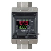
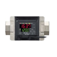
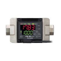
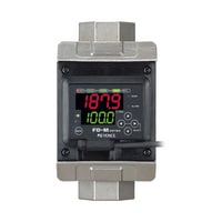
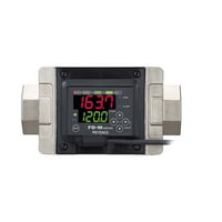
Non-Wetted Electrode Electromagnetic Flow Sensors
FD-M series
Specs Non-Wetted Electrode Electromagnetic Flow Sensors FD-M series
|
Model |
FD-M5AT*1 |
FD-M5AY*1 |
FD-M10AT*1 |
FD-M10AY*1 |
FD-M50AT*1 |
FD-M50AY*1 |
FD-M100AT*1 |
FD-M100AY*1 |
|||
|
Image |
|
|
|
|
|
|
|
|
|||
|
Type |
For vertical piping |
For horizontal piping |
For vertical piping |
For horizontal piping |
For vertical piping |
For horizontal piping |
For vertical piping |
For horizontal piping |
|||
|
Shape |
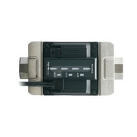
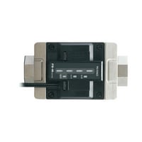
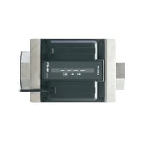
Built-in amplifier |
||||||||||
|
Rated flow range |
0.25 to 5 L/min*2*3 |
0.5 to 10 L/min*2*3 |
2.5 to 50 L/min*2*3 |
5 to 100 L/min*2*3 |
|||||||
|
Possible display range |
0.15 to 10 L/min*4 |
0.5 to 30 L/min*4 |
2.5 to 100 L/min*4 |
5 to 200 L/min*4 |
|||||||
|
Possible ranges to set |
0 to 10 L/min |
0 to 30 L/min |
0 to 100 L/min |
0 to 200 L/min |
|||||||
|
Zero-cut flow rate |
0.15 L/min*5 |
0.5 L/min*5 |
2.5 L/min*5 |
5 L/min*5 |
|||||||
|
Connection diameter |
Rc3/8 (10A) |
Rc3/4 (20A) |
Rc1 (25A) |
||||||||
|
Allowable fluid |
Water or non-corrosive liquid |
||||||||||
|
Conductivity of detection fluids |
5 µS/cm or higher |
||||||||||
|
Detection fluid temperature |
0 to +85°C (No freezing) |
||||||||||
|
Pressure loss |
0.01 MPa or less |
||||||||||
|
Display power |
Dual row display with 4-digit, 7 segment LED, bar display (2 colours), output indicators, flow indicator |
||||||||||
|
Display resolution |
0.05*6/0.1 (L/min) selectable |
0.01/0.1 (L/min) selectable |
0.1/1 (L/min) selectable |
||||||||
|
Repeatability |
0.5 s : ±5% of F.S. |
0.5 s : ±5% of F.S.10 s : ±1% of F.S.1 s : ±3.5% of F.S.30 s : ±0.8% of F.S.2.5 s : ±2.5% of F.S.60 s : ±0.6% of F.S.5 s : ±1.6% of F.S.*9 |
0.5 s : ±5% of F.S. |
||||||||
|
Hysteresis |
Variable |
||||||||||
|
Response time (chatter prevention feature) |
500 ms/1 s/2.5 s/5 s/10 s/30 s/60 s variable |
||||||||||
|
Accumulated flow unit |
0.01/0.1/1/10/100 (L) selectable |
0.1/1/10/100/1000 (L) selectable |
|||||||||
|
Accumulation data storage cycle |
Save to memory every 10 seconds |
||||||||||
|
Memory backup |
EEPROM (Data storage length : 10 years or longer, Data read/write frequency : 1 million times or more) |
||||||||||
|
Control output |
NPN open collector, max. 100 mA/ch*8 (40 V or less), residual voltage 1 V or less, 3 outputs (N.O./N.C. switchable) |
||||||||||
|
Analogue output |
4-20 mA, max. load resistance 260Ω, Analogue output range can be set to any value |
||||||||||
|
Integration reset/bank switch input/flow zero function input |
Input time : 20 ms or greater, Either accumulation reset or bank switching mode can be selected |
||||||||||
|
Power/current consumption |
Normal : 1700 mW (70 mA), Power save : 1000 mW (40 mA) |
||||||||||
|
Rating |
Power voltage |
24 VDC, Ripple (P-P) 10 % or less |
|||||||||
|
Environmental resistance |
Enclosure rating |
IP65 |
|||||||||
|
Pressure resistance |
2.0 MPa |
||||||||||
|
Applied pressure range |
1.0 MPa or less |
||||||||||
|
Ambient temperature |
0 to +50 °C (No freezing) |
||||||||||
|
Relative humidity |
35 to 85 % RH (No condensation) |
||||||||||
|
Vibration resistance |
10 to 55 Hz, Double amplitude 1.5 mm, 2 hours in each of the X, Y, and Z directions |
||||||||||
|
Material |
Liquid end materials |
Bore : SCS13, Measurement pipe : PPS, O ring : fluoro-rubber (FKM) |
|||||||||
|
Material properties |
Other parts |
Plastic case areas : PPS, Metal case areas : SUS430, Cable : PVC |
|||||||||
|
Accessories |
Instruction manual |
||||||||||
|
Weight |
Approx. 835 g |
Approx. 1,100 g |
Approx. 1,310 g |
||||||||
|
*1 The models with “A” at the end of the name have additional functions such as display averaging. |
|||||||||||


|
Model |
FD-M5AYP*1 |
FD-M10ATP*1 |
FD-M10AYP*1 |
FD-M100ATP*1 |
FD-M100AYP*1 |
|||
|
Image |
|
|
|
|
|
|||
|
Type |
For horizontal piping |
For vertical piping |
For horizontal piping |
For vertical piping |
For horizontal piping |
|||
|
Shape |
Built-in amplifier |
|||||||
|
Rated flow range |
0.25 to 5 L/min*2*3 |
0.5 to 10 L/min*2*3 |
5 to 100 L/min*2*3 |
|||||
|
Possible display range |
0.15 to 10 L/min*4 |
0.5 to 30 L/min*4 |
5 to 200 L/min*4 |
|||||
|
Possible ranges to set |
0 to 10 L/min |
0 to 30 L/min |
0 to 200 L/min |
|||||
|
Zero-cut flow rate |
0.15 L/min*5 |
0.5 L/min*5 |
5 L/min*5 |
|||||
|
Connection diameter |
Rc3/8 (10A) |
Rc1 (25A) |
||||||
|
Allowable fluid |
Water or non-corrosive liquid |
|||||||
|
Conductivity of detection fluids |
5 µS/cm or higher |
|||||||
|
Detection fluid temperature |
0 to +85°C (No freezing) |
|||||||
|
Pressure loss |
0.01 MPa or less |
|||||||
|
Display power |
Dual row display with 4-digit, 7 segment LED, bar display (2 colours), output indicators, flow indicator |
|||||||
|
Display resolution |
0.05*6/0.1 (L/min) selectable |
0.01/0.1 (L/min) selectable |
0.1/1 (L/min) selectable |
|||||
|
Repeatability |
0.5 s : ±5% of F.S. |
0.5 s : ±5% of F.S.10 s : ±1% of F.S.1 s : ±3.5% of F.S.30 s : ±0.8% of F.S.2.5 s : ±2.5% of F.S.60 s : ±0.6% of F.S.5 s : ±1.6% of F.S.*9 |
0.5 s : ±5% of F.S. |
|||||
|
Hysteresis |
Variable |
|||||||
|
Response time (chatter prevention feature) |
500 ms/1 s/2.5 s/5 s/10 s/30 s/60 s variable |
|||||||
|
Accumulated flow unit |
0.01/0.1/1/10/100 (L) selectable |
0.1/1/10/100/1000 (L) selectable |
||||||
|
Accumulation data storage cycle |
Save to memory every 10 seconds |
|||||||
|
Memory backup |
EEPROM (Data storage length : 10 years or longer, Data read/write frequency : 1 million times or more) |
|||||||
|
Control output |
PNP open collector, max. 100 mA/ch*8 (30 V or less), residual voltage 1 V or less, 3 outputs (N.O./N.C. switchable) |
|||||||
|
Analogue output |
4-20 mA, max. load resistance 260Ω, Analogue output range can be set to any value |
|||||||
|
Integration reset/bank switch input/flow zero function input |
Input time : 20 ms or greater, Either accumulation reset or bank switching mode can be selected |
|||||||
|
Power/current consumption |
Normal : 1700 mW (70 mA), Power save : 1000 mW (40 mA) |
|||||||
|
Rating |
Power voltage |
24 VDC, Ripple (P-P) 10 % or less |
||||||
|
Environmental resistance |
Enclosure rating |
IP65 |
||||||
|
Pressure resistance |
2.0 MPa |
|||||||
|
Applied pressure range |
1.0 MPa or less |
|||||||
|
Ambient temperature |
0 to +50 °C (No freezing) |
|||||||
|
Relative humidity |
35 to 85 % RH (No condensation) |
|||||||
|
Vibration resistance |
10 to 55 Hz, Double amplitude 1.5 mm, 2 hours in each of the X, Y, and Z directions |
|||||||
|
Material |
Liquid end materials |
Bore : SCS13, Measurement pipe : PPS, O ring : fluoro-rubber (FKM) |
||||||
|
Material properties |
Other parts |
Plastic case areas : PPS, Metal case areas : SUS430, Cable : PVC |
||||||
|
Accessories |
Instruction manual |
|||||||
|
Weight |
Approx. 835 g |
Approx. 1,310 g |
||||||
|
*1 The models with “A” at the end of the name have additional functions such as display averaging. |
||||||||


|
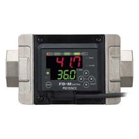
Model |
FD-MH10A*1 |
FD-MH50A*1 |
FD-MH100A*1 |
FD-MH500A*1 |
|||
|
Image |
|
|
|
|
|||
|
Shape |
Separate amplifier |
||||||
|
Rated flow range |
0.5 to 10 L/min*2*3 |
2.5 to 50 L/min*2*3 |
5 to 100 L/min*2*3 |
25 to 500 L/min*2*3 |
|||
|
Possible display range |
0.5 to 30 L/min*4 |
2.5 to 100 L/min*4 |
5 to 200 L/min*4 |
25 to 1000 L/min*4 |
|||
|
Connection diameter |
Rc3/8 (10A) |
Rc3/4 (20A) |
Rc1 (25A) |
Rc2 (50A) |
|||
|
Allowable fluid |
Water or non-corrosive fluid |
||||||
|
Conductivity of detection fluids |
5 µS/cm or higher |
With 25-500 L/min : 5 µS/cm or higher |
|||||
|
Detection fluid temperature |
0 to +85°C (No freezing) |
||||||
|
Pressure loss |
0.01 MPa or less |
0.01 MPa max.*5 |
|||||
|
Display power |
Bar display (2 colours), other indicators |
||||||
|
Environmental resistance |
Enclosure rating |
IP67 |
|||||
|
Pressure resistance |
2.0 MPa |
||||||
|
Applied pressure range |
1.0 MPa or less |
||||||
|
Ambient temperature |
0 to +50 °C (No freezing) |
||||||
|
Relative humidity |
35 to 85 % RH (No condensation) |
||||||
|
Vibration resistance |
10 to 55 Hz, Double amplitude 1.5 mm, 2 hours in each of the X, Y, and Z directions |
||||||
|
Material |
Liquid end materials |
Bore : SCS13, Measurement pipe : PPS, O ring : fluoro-rubber (FKM) |
|||||
|
Material properties |
Other parts |
Plastic case areas : PBT, Indicator : polyalylate, Metal case areas : SUS430, Cable : PVC |
|||||
|
Accessories |
Warnings |
||||||
|
Weight |
Approx. 800 g |
Approx. 1,070 g |
Approx. 1,280 g |
Approx. 3,700 g |
|||
|
*1 The models with “A” at the end of the name support the amplifier type A. They operate normally even when connecting the conventional amplifier without “A” at the end. |
|||||||

|
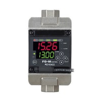
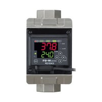
Model |
FD-MA1A*1 |
FD-MA1AP*1 |
FD-MA5AP*1 |
|||
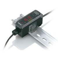
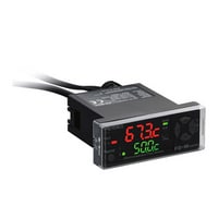
|
Image |
|
|
|
|||
|
Type |
DIN mounted*2 (Main unit) |
Panel mounted*7 |
||||
|
Rated flow range |
FD-MH10A : 0.5 to 10L/min, FD-MH50A : 2.5 to 50L/min, FD-MH100A : 5 to 100L/min, FD-MH500A : 25 to 500L/minThe rated flow range indicates the range that is supposed to be used in general.*3 |
|||||
|
Possible display range |
FD-MH10A : 0.5 to 20L/min, FD-MH50A : 2.5 to 100L/min, FD-MH100A : 5 to 200L/min, FD-MH500A : 25 to 1000L/min*4 |
|||||
|
Possible ranges to set |
FD-MH10A : 0 to 20 L/min,FD-MH50A : 0 to 100 L/min,FD-MH100A : 0 to 200 L/min,FD-MH500A : 0-999.9 L/min |
|||||
|
Zero-cut flow rate |
FD-MH10A : 0.5L/min, FD-MH50A : 2.5L/min, FD-MH100A : 5L/min, FD-MH500A : 25L/min*4 |
|||||
|
Display power |
Dual row display with 4-digit, 7 segment LED, other indicators |
|||||
|
Display resolution |
FD-MH10A: 0.01/0.1 (L/min) selectable, FD-MH50A: 0.1/1 (L/min) selectable, FD-MH100A: 0.1/1 (L/min) selectable, FD-MH500A: 0.1/1 (L/min) selectable |
|||||
|
Repeatability |
0.5 s : ±5% of F.S.,1 s : ±3.5% of F.S., 2.5 s : ±2.5% of F.S., 5 s : ±1.6% of F.S., 10 s : ±1% of F.S., 30 s : ±0.8% of F.S., 60 s : ±0.6% of F.S.*5 |
|||||
|
Hysteresis |
Variable |
|||||
|
Response time (chatter prevention feature) |
500 ms/1 s/2.5 s/5 s/10 s/30 s/60 s variable |
|||||
|
Accumulated flow unit |
FD-MH10A : 0.01/0.1/1/10/100 (ℓ) selectable,FD-MH50A : 0.1/1/10/100/1000 (ℓ) selectable,FD-MH100A : 0.1/1/10/100/1000 (ℓ) selectable,FD-MH500A : 1/10/100/1000/10000 (ℓ) selectable |
|||||
|
Accumulation data storage cycle |
Save to memory every 10 seconds |
|||||
|
Memory backup |
EEPROM (Data storage length : min. 10 years, Data read/write frequency : min. 1 million times) |
|||||
|
Control output |
Maximum NPN open-collector output : 100 mA/ch*6 (40 V or less) |
Maximum PNP open-collector output : 100 mA/ch*6 (30 V or less) |
||||
|
Analogue output |
4-20 mA, max. load resistance 260Ω, Analogue output range can be set to any value |
|||||
|
Integration reset/bank switch input/flow zero function input |
|input time : 20 ms or greater, Either accumulation reset or bank switching mode can be selected |
|||||
|
Power/current consumption |
Normal : 1700 mW (70 mA), Power save : 1440 mW (60 mA) |
|||||
|
Rating |
Power voltage |
24 VDC, Ripple (P-P) 10 % or less |
||||
|
Environmental resistance |
Ambient temperature |
0 to +50 °C (No freezing) |
||||
|
Relative humidity |
35 to 85 % RH (No condensation) |
|||||
|
Vibration resistance |
10 to 55 Hz, Double amplitude 1.5 mm, 2 hours in each of the X, Y, and Z directions |
|||||
|
Material |
Main case : polycarbonate, Key tops : polyacetal, Front sheet : polycarbonate, Cable : PVC |
|||||
|
Accessories |
instruction manual |
Panel mounting bracket, front protective cover, instruction manual |
||||
|
Weight |
Approx. 115 g |
Approx. 105 g |
||||
|
*1 The models with “A” at the end of the name have additional functions such as display averaging. Use the head with “A” at the end of the name. When connecting conventional heads without “A” at the end, the FD-MH operates in the same way |
||||||

|
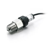
Model |
FD-T1 |
|||
|
Image |
|
|||
|
Connected model |
FD-MH10A/50A/100A/500A*1 |
|||
|
Display, alarm outputcompatible models |
FD-MA1A (P)/MA2A (P)/MA5A (P) |
|||
|
Possible ranges to set |
0.1 to +99.9°C (No freezing) |
|||
|
Connection diameter |
R3/8 (10A) |
|||
|
Detectable temperature range |
0 to 90.0°C (No freezing)*2 |
|||
|
Possible detection fluid |
Water or non-corrosive fluid |
|||
|
Display resolution |
0.1°C |
|||
|
Display speed |
±2.5°C |
|||
|
Display / Output response |
5 s *3 |
|||
|
Hysteresis |
1°C fixed*4 |
|||
|
Alarm output |
Window settings x1 output |
|||
|
Power/current consumption |
2 µW (20 µA) : When using 85°C*5 |
|||
|
Environmental resistance |
Enclosure rating |
IP67 |
||
|
Pressure resistance |
2.0 MPa |
|||
|
Applied pressure range |
1.0 MPa or less |
|||
|
Ambient temperature |
0 to +50 °C (No freezing) |
|||
|
Relative humidity |
35 to 85 % RH (No condensation) |
|||
|
Vibration resistance |
10 to 55 Hz, Double amplitude 1.5 mm, 2 hours in each of the X, Y, and Z directions |
|||
|
Material |
Metal parts : SUS304, Plastic parts : PBT, |
|||
|
Accessories |
None |
|||
|
Weight |
Approx. 130 g |
|||
|
*1 The FD-M built-in type cannot be connected. |
||||