
Separate Amplifier Digital Proximity Sensor
ER-N series
Sensor head Separate amplifier Shielded type Thin type t = 3.5 ER-NH035F
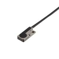
*Please note that accessories depicted in the image are for illustrative purposes only and may not be included with the product.

Specifications
Model | ER-NH035F | |||
Cable | Standard | |||
Stable detection range | 0 to 1 mm | |||
Maximum operating distance | 3 mm 0.12" *1 *3 | |||
Hysteresis distance | Adjustable | |||
Repeatability | 1 μm 0.04 Mil *1 *4 | |||
Detectable object | Magnetic metal, Non-magnetic metal *5 | |||
Standard detectable object (Iron, t = 1 mm) | 5 × 5 mm | |||
Temperature characteristics | ±10% or less of detecting distance at +25°C +77°F (0 to +50°C 32°F to 122°F) | |||
Environmental resistance | Enclosure rating | IP67 (IEC60529) | ||
Ambient temperature | -10 to +60°C 14°F to 140°F (no freezing) | |||
Relative humidity | Up to 85% RH (No condensation) | |||
Vibration resistance | 10 to 500 Hz; Power spectral density: 0.816 G2/Hz; X, Y, and Z directions | |||
Shock resistance | 1000 m/s2 3280.8 ft/s2 (100 G), 10 times in each of the X, Y, and Z directions | |||
Material | Detection surface | Epoxy resin | ||
Case | SUS304 | |||
Cable | PVC | |||
Sensor head connector | PA66, polycarbonate | |||
Accessories | M2 screw/nut/spring washer/ | |||
Accessories | M2 screw/nut/ | |||
Weight | Approx. 40 g | |||
*1 The stable detection range, maximum operating distance, repeatability, and temperature characteristics are values for when the operation mode is set to “Normal” using a standard detection object. | ||||