Separate Amplifier Digital Proximity Sensor
ER-N series
Characteristic Diagrams Separate Amplifier Digital Proximity Sensor ER-N series
ER-NH028
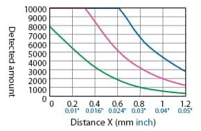
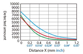
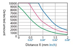
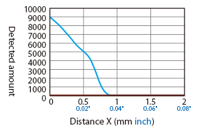
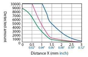
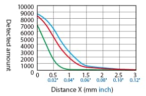
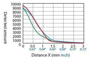
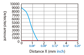
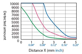
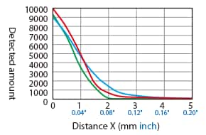
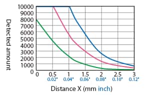
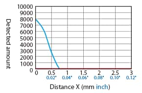
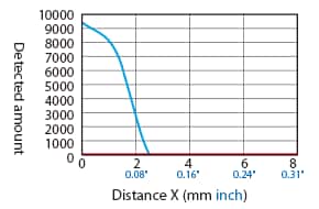
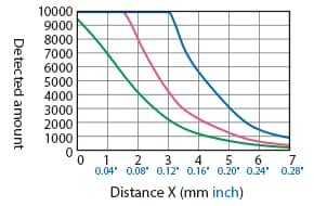
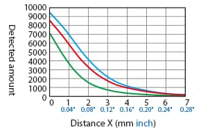
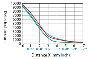
Distance – Detection Amount Characteristics (Typical Example)
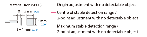
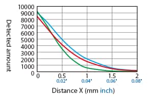
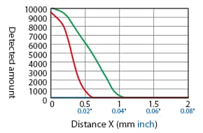
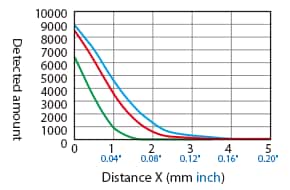
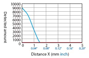
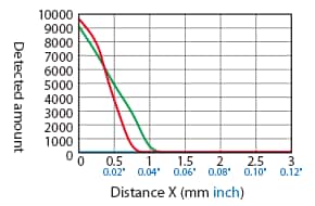
Difference in Characteristics According to Adjustment Conditions (Operation Mode: Normal)
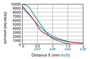
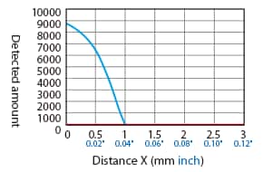
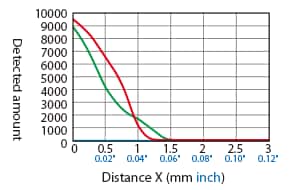
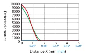
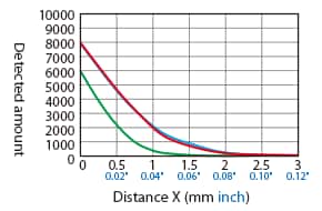
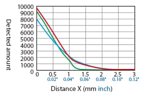
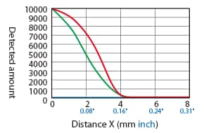
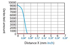
Difference in Characteristics According to Operation Mode (Origin Adjustment With No Detectable Object)
[Operation mode: Normal]
[Operation mode: Hybrid]
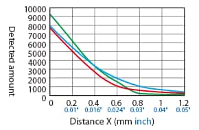
[Operation mode: Magnetic metal]
[Operation mode: Non-magnetic metal]
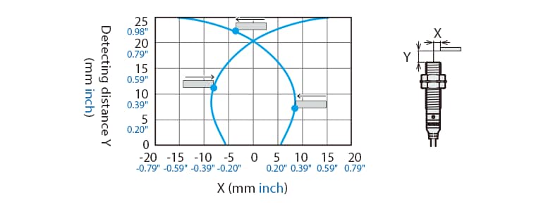
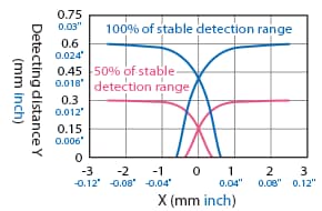
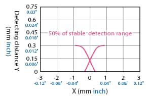
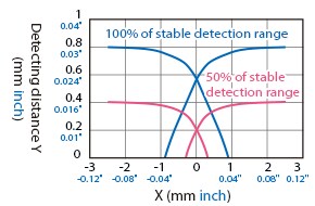
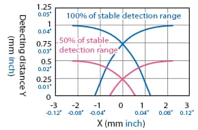
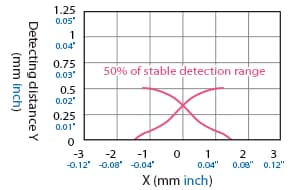
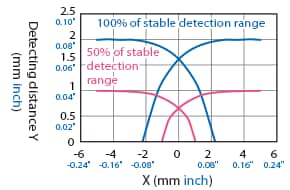
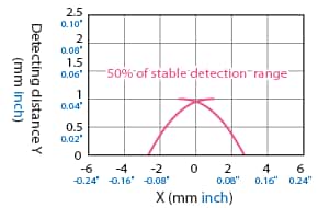
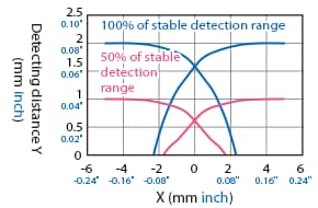
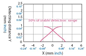
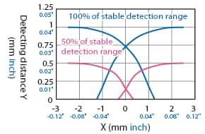
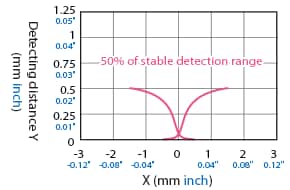
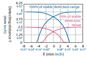
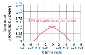
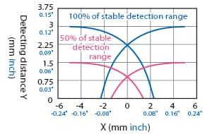
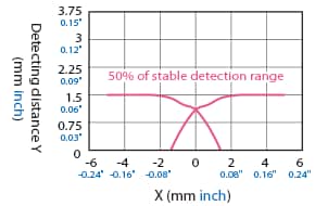
Detection Area Diagram (Typical Example)
When the origin is adjusted with no detectable object, and when the centre of the sensor is aligned with and facing the detectable object at a distance of 100% or 50% of the stable detection range, the displayed value is used as the set value.

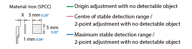
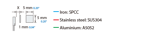
Detectable Object Size: 5 mm × 5 mm 0.20″ × 0.20″, Thickness t = 1 mm 0.04″ (Standard Detectable Object Size), Normal Mode
Detectable object: Iron (SPCC)
Detectable object: Aluminium (A5052)
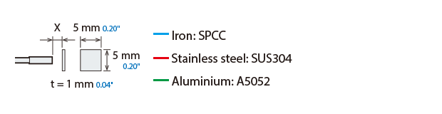
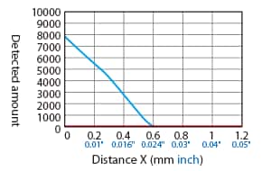
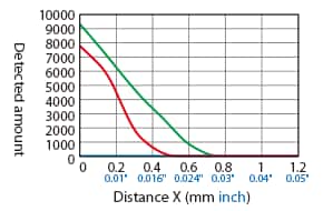
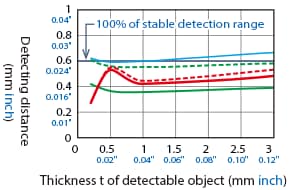
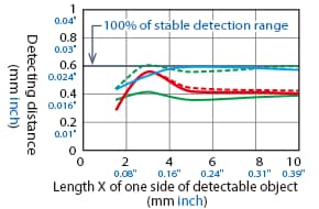
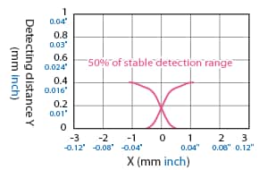
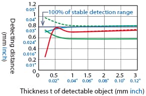
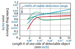
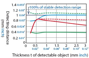
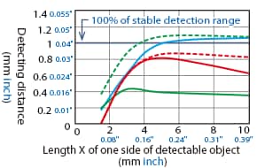
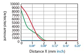
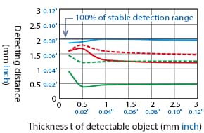
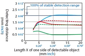
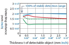
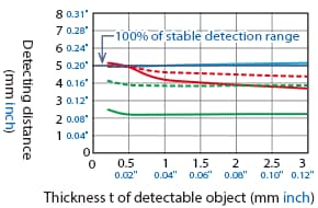
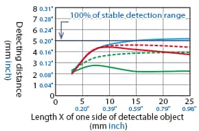
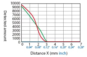
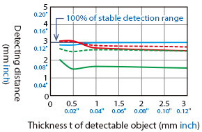
Variation of Detecting Distance According to the Size and Material of the Detectable Object (Typical Example)
When a standard detectable object is placed at 50% of the stable detection range, and when 2-point adjustment is performed with no detectable object, the value displayed when the standard detectable object is at 100% of the stable detection range is used as the set value. The detecting distance becomes shorter when the operating mode is set to magnetic/non-magnetic metal.
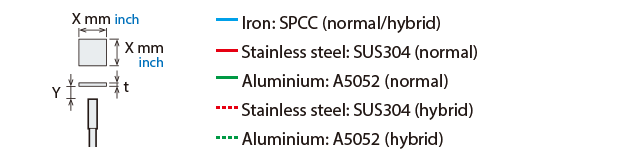
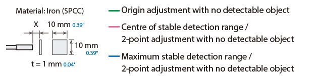
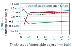
Detectable Object Size: 5 mm × 5 mm 0.20″ × 0.20″, Thickness = t mm
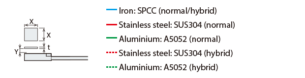
Effect of thickness of detectable object
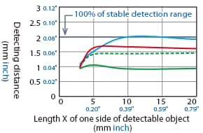
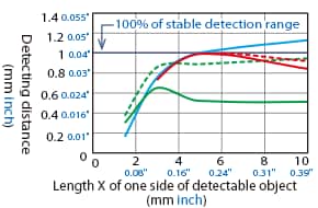
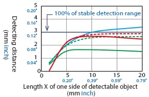
Detectable Object Size: X × X, Thickness t = 1 mm 0.04″
Effect of size of detectable object
ER-NH038
Distance – Detection Amount Characteristics (Typical Example)
Difference in Characteristics According to Adjustment Conditions (Operation Mode: Normal)
Difference in Characteristics According to Operation Mode (Origin Adjustment With No Detectable Object)
[Operation mode: Normal]
[Operation mode: Hybrid]
[Operation mode: Magnetic metal]
[Operation mode: Non-magnetic metal]
Detection Area Diagram (Typical Example)
When the origin is adjusted with no detectable object, and when the centre of the sensor is aligned with and facing the detectable object at a distance of 100% or 50% of the stable detection range, the displayed value is used as the set value.
Detectable Object Size: 5 mm × 5 mm 0.20″ × 0.20″, Thickness t = 1 mm 0.04″ (Standard Detectable Object Size), Normal Mode
Detectable object: Iron (SPCC)
Detectable object: Aluminium (A5052)
Variation of Detecting Distance According to the Size and Material of the Detectable Object (Typical Example)
When a standard detectable object is placed at 50% of the stable detection range, and when 2-point adjustment is performed with no detectable object, the value displayed when the standard detectable object is at 100% of the stable detection range is used as the set value. The detecting distance becomes shorter when the operating mode is set to magnetic/non-magnetic metal.
Detectable Object Size: 5 mm × 5 mm 0.20″ × 0.20″, Thickness = t mm
Effect of thickness of detectable object
Detectable Object Size: X × X, Thickness t = 1 mm 0.04″
Effect of size of detectable object
ER-NH054(G)
Distance – Detection Amount Characteristics (Typical Example)
Difference in Characteristics According to Adjustment Conditions (Operation Mode: Normal)
Difference in Characteristics According to Operation Mode (Origin Adjustment With No Detectable Object)
[Operation mode: Normal]
[Operation mode: Hybrid]
[Operation mode: Magnetic metal]
[Operation mode: Non-magnetic metal]
Detection Area Diagram (Typical Example)
When the origin is adjusted with no detectable object, and when the centre of the sensor is aligned with and facing the detectable object at a distance of 100% or 50% of the stable detection range, the displayed value is used as the set value.
Detectable Object Size: 5 mm × 5 mm 0.20″ × 0.20″, Thickness t = 1 mm 0.04″ (Standard Detectable Object Size), Normal Mode
Detectable object: Iron (SPCC)
Detectable object: Aluminium (A5052)
Variation of Detecting Distance According to the Size and Material of the Detectable Object (Typical Example)
When a standard detectable object is placed at 50% of the stable detection range, and when 2-point adjustment is performed with no detectable object, the value displayed when the standard detectable object is at 100% of the stable detection range is used as the set value. The detecting distance becomes shorter when the operating mode is set to magnetic/non-magnetic metal.
Detectable Object Size: 5 mm × 5 mm 0.20″ × 0.20″, Thickness = t mm
Effect of thickness of detectable object
Detectable Object Size: X × X, Thickness t = 1 mm 0.04″
Effect of size of detectable object
ER-NH080(G)
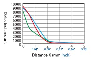
Distance – Detection Amount Characteristics (Typical Example)
Difference in Characteristics According to Adjustment Conditions (Operation Mode: Normal)
Difference in Characteristics According to Operation Mode (Origin Adjustment With No Detectable Object)
[Operation mode: Normal]
[Operation mode: Hybrid]
[Operation mode: Magnetic metal]
[Operation mode: Non-magnetic metal]
Detection Area Diagram (Typical Example)
When the origin is adjusted with no detectable object, and when the centre of the sensor is aligned with and facing the detectable object at a distance of 100% or 50% of the stable detection range, the displayed value is used as the set value.
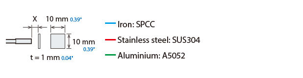
Detectable Object Size: 10 mm × 10 mm 0.39″ × 0.39″, Thickness t = 1 mm 0.04″ (Standard Detectable Object Size), Normal Mode
Detectable object: Iron (SPCC)
Detectable object: Aluminium (A5052)
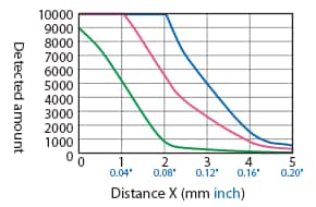
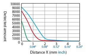
Variation of Detecting Distance According to the Size and Material of the Detectable Object (Typical Example)
When a standard detectable object is placed at 50% of the stable detection range, and when 2-point adjustment is performed with no detectable object, the value displayed when the standard detectable object is at 100% of the stable detection range is used as the set value. The detecting distance becomes shorter when the operating mode is set to magnetic/non-magnetic metal.
Detectable Object Size: 10 mm × 10 mm 0.39″ × 0.39″, Thickness = t mm
Effect of thickness of detectable object
Detectable Object Size: X × X, Thickness t = 1 mm 0.04″
Effect of size of detectable object
ER-NH100(G)
Distance – Detection Amount Characteristics (Typical Example)
Difference in Characteristics According to Adjustment Conditions (Operation Mode: Normal)
Difference in Characteristics According to Operation Mode (Origin Adjustment With No Detectable Object)
[Operation mode: Normal]
[Operation mode: Hybrid]
[Operation mode: Magnetic metal]
[Operation mode: Non-magnetic metal]
Detection Area Diagram (Typical Example)
When the origin is adjusted with no detectable object, and when the centre of the sensor is aligned with and facing the detectable object at a distance of 100% or 50% of the stable detection range, the displayed value is used as the set value.
Detectable Object Size: 10 mm × 10 mm 0.39″ × 0.39″, Thickness t = 1 mm 0.04″ (Standard Detectable Object Size), Normal Mode
Detectable object: Iron (SPCC)
Detectable object: Aluminium (A5052)
Variation of Detecting Distance According to the Size and Material of the Detectable Object (Typical Example)
When a standard detectable object is placed at 50% of the stable detection range, and when 2-point adjustment is performed with no detectable object, the value displayed when the standard detectable object is at 100% of the stable detection range is used as the set value. The detecting distance becomes shorter when the operating mode is set to magnetic/non-magnetic metal.
Detectable Object Size: 10 mm × 10 mm 0.39″ × 0.39″, Thickness = t mm
Effect of thickness of detectable object
Detectable Object Size: X × X, Thickness t = 1 mm 0.04″
Effect of size of detectable object
ER-NH035F
Distance – Detection Amount Characteristics (Typical Example)
Difference in Characteristics According to Adjustment Conditions (Operation Mode: Normal)
Difference in Characteristics According to Operation Mode (Origin Adjustment With No Detectable Object)
[Operation mode: Normal]
[Operation mode: Hybrid]
[Operation mode: Magnetic metal]
[Operation mode: Non-magnetic metal]
Detection Area Diagram (Typical Example)
When the origin is adjusted with no detectable object, and when the centre of the sensor is aligned with and facing the detectable object at a distance of 100% or 50% of the stable detection range, the displayed value is used as the set value.

Detectable Object Size: 5 mm × 5 mm 0.20″ × 0.20″, Thickness t = 1 mm 0.04″ (Standard Detectable Object Size), Normal Mode
Detectable object: Iron (SPCC)
Detectable object: Aluminium (A5052)
Variation of Detecting Distance According to the Size and Material of the Detectable Object (Typical Example)
When a standard detectable object is placed at 50% of the stable detection range, and when 2-point adjustment is performed with no detectable object, the value displayed when the standard detectable object is at 100% of the stable detection range is used as the set value. The detecting distance becomes shorter when the operating mode is set to magnetic/non-magnetic metal.
Detectable Object Size: 5 mm × 5 mm 0.20″ × 0.20″, Thickness = t mm
Effect of thickness of detectable object
Detectable Object Size: X × X, Thickness t = 1 mm 0.04″
Effect of size of detectable object
ER-NH048F
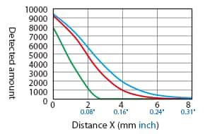
Distance – Detection Amount Characteristics (Typical Example)
Difference in Characteristics According to Adjustment Conditions (Operation Mode: Normal)
Difference in Characteristics According to Operation Mode (Origin Adjustment With No Detectable Object)
[Operation mode: Normal]
[Operation mode: Hybrid]
[Operation mode: Magnetic metal]
[Operation mode: Non-magnetic metal]
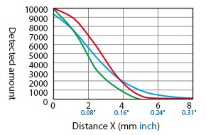
Detection Area Diagram (Typical Example)
When the origin is adjusted with no detectable object, and when the centre of the sensor is aligned with and facing the detectable object at a distance of 100% or 50% of the stable detection range, the displayed value is used as the set value.
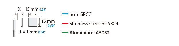
Detectable Object Size: 15 mm × 15 mm 0.59″ × 0.59″, Thickness t = 1 mm 0.04″ (Standard Detectable Object Size), Normal Mode
Detectable object: Iron (SPCC)
Detectable object: Aluminium (A5052)
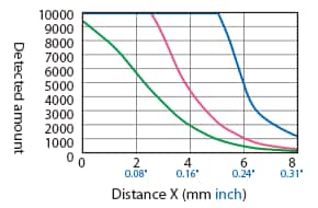
Variation of Detecting Distance According to the Size and Material of the Detectable Object (Typical Example)
When a standard detectable object is placed at 50% of the stable detection range, and when 2-point adjustment is performed with no detectable object, the value displayed when the standard detectable object is at 100% of the stable detection range is used as the set value. The detecting distance becomes shorter when the operating mode is set to magnetic/non-magnetic metal.
Detectable Object Size: 15 mm × 15 mm 0.59″ × 0.59″, Thickness = t mm
Effect of thickness of detectable object
Detectable Object Size: X × X, Thickness t = 1 mm 0.04″
Effect of size of detectable object
ER-NH028U
Distance – Detection Amount Characteristics (Typical Example)
Difference in Characteristics According to Adjustment Conditions (Operation Mode: Normal)
Difference in Characteristics According to Operation Mode (Origin Adjustment With No Detectable Object)
[Operation mode: Normal]
[Operation mode: Hybrid]
[Operation mode: Magnetic metal]
[Operation mode: Non-magnetic metal]
Detection Area Diagram (Typical Example)
When the origin is adjusted with no detectable object, and when the centre of the sensor is aligned with and facing the detectable object at a distance of 100% or 50% of the stable detection range, the displayed value is used as the set value.
Detectable Object Size: 10 mm × 10 mm 0.39″ × 0.39″, Thickness t = 1 mm 0.04″ (Standard Detectable Object Size), Normal Mode
Detectable object: Iron (SPCC)
Detectable object: Aluminium (A5052)
Variation of Detecting Distance According to the Size and Material of the Detectable Object (Typical Example)
When a standard detectable object is placed at 50% of the stable detection range, and when 2-point adjustment is performed with no detectable object, the value displayed when the standard detectable object is at 100% of the stable detection range is used as the set value. The detecting distance becomes shorter when the operating mode is set to magnetic/non-magnetic metal.
Detectable Object Size: 10 mm × 10 mm 0.39″ × 0.39″, Thickness = t mm
Effect of thickness of detectable object
Detectable Object Size: X × X, Thickness t = 1 mm 0.04″
Effect of size of detectable object
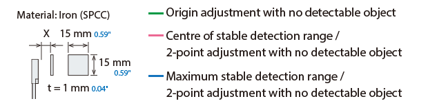
How To Read Detection Area Diagrams
The following shows the position of the ON point when the standard detectable object (specified in the specifications) is moved parallel to the sensor in the direction of the arrow.