
Form Tolerance (Form Deviation)
Form tolerance is a basic geometric tolerance that determines the form of the target (part). None of the characteristics of form tolerance require a datum—forms can be independently determined.
Straightness
The straightness requirement specifies how perfectly straight a target should be. It is applied to lines and not planes, and represents a curve in the centre line or generatrix. Therefore, straightness is used to indicate the warpage tolerance of long objects.
- Explanation of drawings
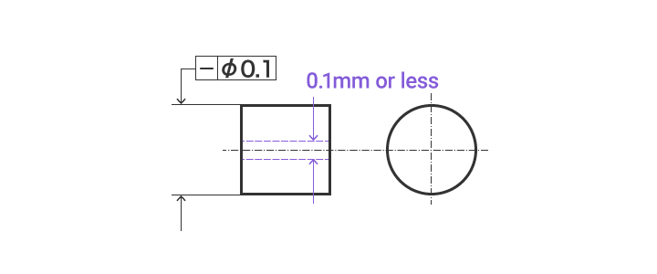
- If a tolerance frame is connected to the size indicating the diameter of a cylinder, the axis of that cylinder must be within a cylinder with a diameter of 0.1 mm.
Flatness

The flatness requirement specifies the evenness of a surface, or how accurately flat a target plane should be. The most protruding part and the most concaved part must be at a specific distance between two planes that are separated vertically.
- Explanation of drawings
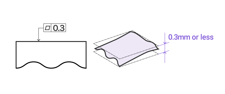
- This surface must be between two parallel planes separated by only 0.3 mm.
Roundness

The roundness requirement specifies how perfectly circular a target—the circular cross-section of a shaft, bore, or cone—should be.
- Explanation of drawings
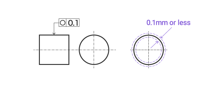
- The outer circumference of any cross-section of a shaft cut perpendicularly should be between two concentric circles just 0.1 mm apart on the same plane.
Cylindricity

The cylindricity requirement specifies how accurately circular and straight a target cylinder is. The value represents any distortion in a cylinder.
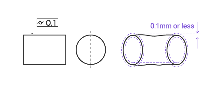
- Explanation of drawings
- The target plane must be between two coaxial cylinders just 0.1 mm apart.
