GD&T Symbols

GD&T Symbols

Form Tolerance
Straightness
Straightness
Used to specify how straight a target is.
Flatness
Flatness
Used to specify the most protruded part and the most concaved part.
Roundness
Roundness
Used to specify how close a target should be to a perfect circle.
Cylindricity
Cylindricity
Used to specify how straight a target is and how close the target should be to a perfect circle.
Profile tolerance of line
Used to specify how close a curvature (cross-section) is to the design.
Profile tolerance of plane
Used to specify how close a curvature (surface) is to the design.
Orientation Tolerance
Parallelism
Parallelism
Used to specify how accurately parallel two lines or planes are to the datum.
Perpendicularity
Perpendicularity
Used to specify how accurately perpendicular a target is to the datum.
Angularity
Angularity
Used to specify how accurately angled a target is to the datum.
Location Tolerance
True position
True position
Used to specify how accurately a target is positioned in relation to the datum.
Coaxiality and Concentricity
Coaxiality
Used to specify that the axes of two cylinders are coaxial (no deviation in central axes) to the datum.
Concentricity
Used to specify that the axes of two cylinders are coaxial (no deviation in centre points) to the datum.
Symmetry
Symmetry
Used to specify how symmetrical a target is to the datum.
Runout Tolerance
Circular runout
Circular runout
Used to specify the runout of any part of a circumference when a target is rotated.
Total runout
Total runout
Used to specify the runout of the entire surface when a target is rotated.

Associated Symbols

Envelope Requirement
“E” stands for “envelope.” This symbol indicates the mutual dependency of size tolerance and geometric tolerance. It specifies the envelope of perfect form.
Free state of non-rigid parts
“F” stands for “free state.” This symbol indicates a deformation beyond size tolerance or geometric tolerance under a free state.
Application of least material condition
“L” stands for “least material condition.” This symbol indicates the application of least material condition.
Application of maximum material condition
“M” stands for “maximum material condition.” This symbol indicates the application of maximum material condition.
Indication of projected tolerance zone
“P” stands for “projected tolerance zone.” This symbol indicates the tolerance applied to the protrusion of a feature.
No material requirement
Symbol used by ANSI standard. It represents “Regardless of Feature Size (RFS).” This symbol has been removed in ASME Y14.5-2009.
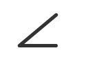
Indication of tangent plane (ASME only)
“T” stands for “tangent plane.” How angled a plane in contact with the surface is to the datum plane within the range of specified surface is indicated by parallelism. Unlike parallelism, this specifies the convex of the surface and not the concave.
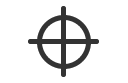
Unequally disposed profile tolerance (ASME only)
“U” stands for “unequally disposed profile.” This specifies the range of runout of the offset amount from the tolerance zone (tolerance zone limit) in terms of the profile tolerance of a plane. “UZ” is used for annotation according to the ISO standards.
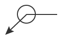
Toleranced feature
Toleranced feature
Indication of symbols, tolerances, types of geometric tolerances, position, and other requirements.
Datum indication
Datum indication
Datum position.
Datum target
Datum target
Point, line, or zone for establishing a datum.
Theoretically exact dimension (TED)
Common tolerance zone
“CZ” stands for common zone. Indication that multiple features in separated positions are deemed as a single tolerance zone.
Profile tolerance (perimeter)
Means to apply geometric tolerance to the perimeter of the feature indicated by an arrow.
Profile tolerance (entirety)
Means to apply geometric tolerance to the entirety of the feature indicated by an arrow.
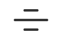
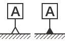
Movable datum target (ASME only; proposed for ISO)
A specified datum target and other datums associated with it can be moved. For example, even when a part is attached to a target, changing the shape of the target, the datum target and the datum can be moved.
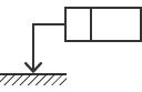
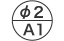
Spot facing (ASME only)
Machining that creates a counterbore enlarges another coaxial hole.
Statistical tolerance (ASME only)
Specification that assigns tolerance to the assembled components according to statistics. By applying statistical tolerance, the tolerance for each component can be increased, reducing the clearance between the components and the mating parts. While this can improve product performance and/or reduce production costs, the application of this tolerance requires appropriate statistical process management as a prerequisite.
Continuous feature (ASME only)
“CF” stands for “continuous feature.” This requirement is indicated when features need to be geometrically treated as a single feature.

INDEX