What Is a Projected Tolerance Zone?
The projected tolerance zone applies to a feature’s protrusion. In most cases, the zone to which geometric tolerance is applied is limited to the range of the feature specified in the drawing. In contrast to this, indications using the projected tolerance zone can specify a virtual zone for the specified feature’s mating part.
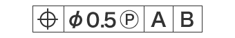
Projected Tolerance Zone Annotation
To indicate the projected tolerance zone, which applies to the range of the mating part, you write after the value of the length of protrusion in the feature control frame.
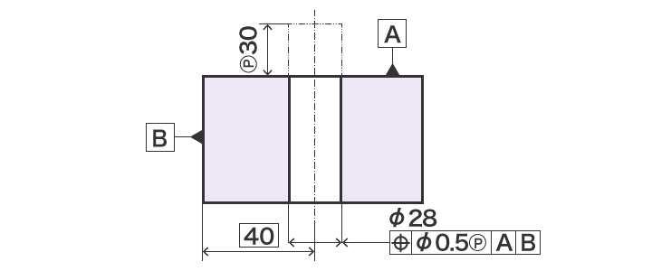
Projected Tolerance Zone Specification Example
The following shows a sample indication that specifies that “the dia. 28 mm shaft centre in the virtual space must be inside a dia. 0.5 mm cylinder throughout the entire length of the 30 mm protrusion of the dia. 28 mm cylinder whose axis is located 40 mm from datum B and perpendicular to datum A.” The protrusion is indicated by a dashed-two dotted line.
This indication enables the manufacture of parts that are guaranteed to fit, provided that their specifications are within tolerance.