GD&T Drawings and Symbols
Geometric tolerances are specified using symbols on a drawing. Currently, we have 16 symbols for geometric tolerances, which are categorised according to the tolerance they specify.
- Classification and Symbols of Geometric Tolerance Characteristics
- True Position Theory (Size Value in Rectangular Frame)
Classification and Symbols of Geometric Tolerance Characteristics
The following is a list of symbols used for geometric tolerancing. “Single feature” under “Feature level” means features that are independent of datums (i.e. that do not require reference datum indication). A datum is a theoretical, ideal feature established to determine the orientation, location, and/or runout. An associated feature is a feature related to a datum, and specifies the orientation tolerance, location tolerance, and/or runout tolerance.
| Feature level | Tolerance type | Geometrical characteristic | Symbol |
|---|---|---|---|
| Single feature | Form tolerance (Form deviation) |
Straightness | 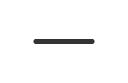 |
| Flatness | 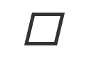 |
||
| Roundness | 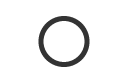 |
||
| Cylindricity | 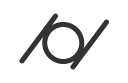 |
||
| Profile tolerance of line | 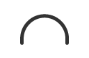 |
||
| Profile tolerance of plane |  |
||
| Associated feature (Requires datum feature) |
Orientation tolerance | Parallelism | 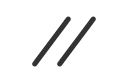 |
| Perpendicularity | 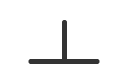 |
||
| Angularity | 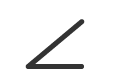 |
||
| Location tolerance (Location deviation) |
True position |  |
|
| Coaxiality |  |
||
| Concentricity | |||
| Symmetry |  |
||
| Profile tolerance of line |  |
||
| Profile tolerance of plane |  |
||
| Runout tolerance (Runout deviation) |
Circular runout |  |
|
| Total runout |  |
| Single feature | |
|---|---|
| Form tolerance (Form deviation) | |
| Straightness | |
| Flatness | |
| Roundness | |
| Cylindricity | |
| Profile tolerance of line | |
| Profile tolerance of plane | |
| Associated feature (Requires datum feature) | |
|---|---|
| Orientation tolerance | |
| Parallelism | |
| Perpendicularity | |
| Angularity | |
| Location tolerance (Location deviation) | |
| True position | |
| Coaxiality | |
| Concentricity | |
| Symmetry | |
| Profile tolerance of line | |
| Profile tolerance of plane | |
| Runout Tolerance (Runout Deviation) | |
| Circular runout | |
| Total runout | |
List of geometric tolerance symbols (Relevant standard: ISO 5459)
True Position Theory (Size Value in Rectangular Frame)
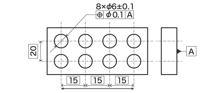
True position theory is the concept of indicating geometrical characteristics (true position, profile, and angularity) using theoretically exact dimensions (TED). The theoretically exact dimensions are written in rectangular frames while the tolerances concerning that position are written in feature control frames.
Specifying the Position
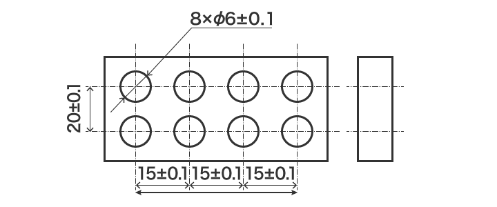
As shown in the drawing below, accurate positions cannot be indicated using size tolerance-based indication, because both the reference dimensions and the tolerances become the total sum of the size tolerance (accumulated tolerance). On the other hand, TED-based indication does not have tolerances, which means that no accumulated tolerance is produced.
Specifying the Tolerance Zone
To specify the tolerance zone, in true position theory, you use TED to accurately indicate the specification at the centre of the tolerance value.
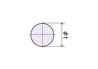
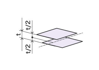
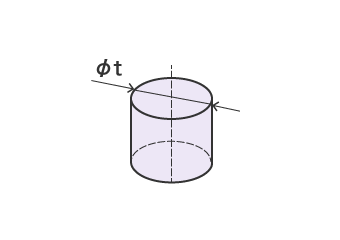
If the feature is a point, the tolerance zone is a circle, (a) or sphere, centring around that point. If the feature is a straight line, then the tolerance zone is between two parallel planes (b), each being precisely separated from that line by half the tolerance value. Alternatively, the tolerance zone can be a cylindrical tolerance zone (c) with that straight line as its central axis.