GD&T of Non-Rigid Parts
Parts like those made of rubber or resin, where deformation beyond what is specified in the drawing is presumed to occur due to a release of internal stress generated during the manufacturing process, are called non-rigid parts.
For non-rigid parts, you will indicate the geometric tolerance in a free state (a state where only the force of gravity is applied). You will also need to indicate that the part is non-rigid and the conditions under which the geometric tolerance under free state is ensured (such as direction of gravity).
Annotations for Non-Rigid Parts
Generally, geometric tolerance applies to rigid parts. For parts that deform beyond size tolerance or geometric tolerance in a free state, you will write after the geometric tolerance in the feature control frame to indicate that the part is a non-rigid target.
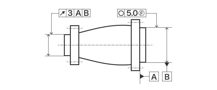
“F” stands for “free state,” and means to apply the tolerance under a free state.

Non-Rigid Part Specification Example
The sample indication below specifies that “in any orientation, datum B must have a roundness within 5.0 mm, and the circular runout on the left side is applied under restrained condition.”