
Major Types of Datum Features
A datum feature can be a plane, line, or point—these are selectively used depending on the tolerance and feature you need to specify.
Datum Plane
A datum plane is a plane on the target that is established as a datum. It can be a target’s external plane (datum plane) or centre plane (datum centre plane).
“Datum plane” is defined as follows in ISO and ASME standards:
- ISO 5459:2011
- A datum that is a theoretically exact plane.
- ASME Y14.5-2009
- The plane of a datum feature simulator established from the datum feature.
Datum Plane
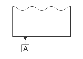
A datum plane is a datum established on an external surface of a target. To use a flat surface as a datum, the following indication symbol is used:
Indication symbol
Datum setting
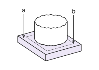
- a
- Simulated datum feature = Surface of surface plate
- b
- Datum = Plane set up by the surface plate
The surface of the target (datum feature) indicated as the datum may be uneven or warped. Datum plane A can be established by supporting the surface set up as a datum using a surface plate or other higher precision plane. The supporting plane is the simulated datum feature.
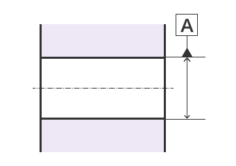
Datum Centre Plane
A datum centre plane is the theoretical plane established on a centre plane of the target. To use the centre plane of two parallel surfaces as a datum, the following indication symbol is used:
Indication symbol
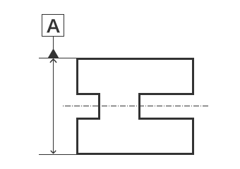
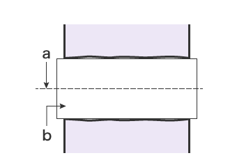
Datum setting
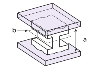
- a
- Simulated datum feature = Two flat contact surfaces
- b
- Datum = Plane set up by two flat contact surfaces
In the same way as a datum plane, the surface of the target (datum feature) specified as a datum may be uneven or warped. The datum centre plane can be established by supporting the surface set up as a datum from both sides using precision planes. The two supporting planes are the simulated datum features. The theoretical plane generated from these features is the datum centre plane.
Datum Line
A datum line is the theoretical straight line established on the centre of a cylinder bore or cylinder shaft, or a ridge such as the target’s edge. A datum line can be a datum axis or datum axis line. A datum line is generally established on the centre of a target’s cylinder bore or cylinder shaft, and is rarely established on a ridge. This section explains cases where a datum axis is established on a cylinder bore and on a cylinder axis. “Datum axis” is defined as follows in ISO and ASME standards:
- ISO 5459:2011
- A datum that is a theoretically exact straight line.
- ASME Y14.5-2009
- The axis of a datum feature simulator established from the datum feature.
Datum axis (cylinder bore)
A datum established on the centre of a cylinder bore is indicated using the following symbol:
Indication symbol
Datum setting
- a
- Datum (datum axis line) = Axis line of maximum inscribed cylinder
- b
- Simulated datum feature = Maximum inscribed cylinder
The surface of the cylinder bore of the target specified as a datum (datum feature) may be uneven or warped. By inserting a precision shaft that closely fits the bore, a datum can be established in this bore. Here, the inserted shaft is the simulated datum feature, and the axis line is the datum axis line.
Datum axis (cylinder shaft)
A datum established on the centre of a cylinder shaft is indicated using the following symbol:
Indication symbol
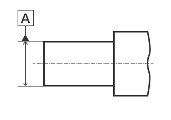
Datum setting
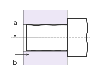
- a
- Datum (datum axis line) = Axis line of minimum circumscribed cylinder
- b
- Simulated datum feature = Minimum circumscribed cylinder
The surface of the cylinder shaft of the target specified as a datum (datum feature) may be uneven or warped. By inserting the shaft into a precision housing that closely fits the shaft, a datum can be established in the housing. Here, the housing is the simulated datum feature, and the axis line is the datum axis line.
Point
A datum point established on the centre of a spherical target is indicated using the following symbol:
Indication symbol
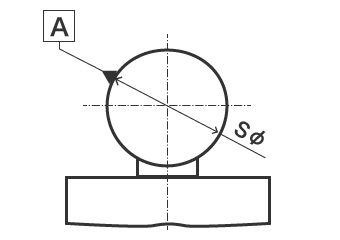
Datum setting
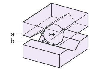
- a
- Datum = Centre of minimum circumscribed sphere
- b
- Simulated datum feature = V-block-style four contact points (expressed by minimum circumscribed sphere)
The spherical surface of the target specified as a datum (datum feature) may be uneven or warped. When four contact points are made with two V-blocks, the datum feature sphere’s surface is the simulated datum feature, and the centre is the datum point.
