International Industrial Standards and GD&T
Along with the globalisation of corporate activities, international standardisation is proceeding in the area of technical drawing, and national standards are periodically revised to be brought in line with the international standards.
Beginning of Standardisation
The provisions for the standardisation of drawings started in 1938 with the Taylor Principle, which aimed to control form tolerance (form deviation) with size tolerance for screw fitting.
Subsequently, the indication of the control of form and location tolerances was discussed in the U.S., Canada, and the UK, which was followed by further discussions on the geometric tolerance approach as a replacement for conventional descriptions.
ISO Standardisation
Since 1950, research has progressed in the use of geometric tolerance symbols in drawings, datum definitions, and maximum material requirement. In 1985, the ISO adopted the principle of independency.
The ISO defines it as follows:
- ISO 8015 “Principle of Independency”
-
Each specified dimensional or geometric tolerance on a drawing shall be met independently, unless a particular relationship is specified.
- Dimensional tolerances do not control form deviations.
- Form deviations are controlled by geometric tolerances.
- A linear tolerance controls only the actual local sizes (two-point measurements) of a feature.
U.S. Standardisation
The American standard organisation has changed from ASA and ANSI to ASME, but they have all adopted the envelope principle. The envelope principle is the concept that the indicated toleranced size also controls the geometrical characteristics if the target is a feature of size. This means that, under the ASME provisions, unlike the ISO, which provides that dimensional and geometric tolerances be separately defined for a feature of size, an indication of dimensional tolerance also doubles as an indication of geometric tolerance.
- ASME Y14.5-2009 “Envelope Principle”
- The indicated toleranced size also controls the geometrical characteristics for a feature of size.
ASME also adopted the independence symbol in 2009. When not applying the envelope principle, the principle of independency is applied using an original symbol; the ASME is becoming more consistent with the ISO in terms of indication.
Comparison of ISO and ASME
Both the ISO and the ASME are active in their pursuit of standardisation, aiming for a globalisation of drawings. However, there are still some differences in symbols and notations. Care must be taken when reading and creating drawings.
Differences in Symbols
Some symbols are different between ISO and ASME standards. As some are currently under review for unification, for these standards you need to verify the latest information.
- Unequally disposed profile tolerance
- ASME: ISO: UZ
- Maximum material boundary
- ASME: ISO: None
- Least material boundary
- ASME: ISO: None
- Contact plane
- ASME: ISO: None
- Parallel movement
- ASME: ISO: None
- Spot facing
- ASME: ISO: None
- Statistical tolerance
- ASME: ISO: None
- Continuous feature
- ASME: ISO: None
- Movable datum target
- ASME: ISO: Proposed
Differences in Interpretation
The details of control may be different even when the indications are the same. The following shows an example, but there are other differences in indications and concepts. For more information, please refer to technical literature.
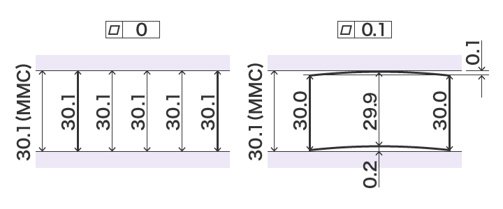
- ISO
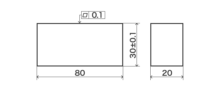
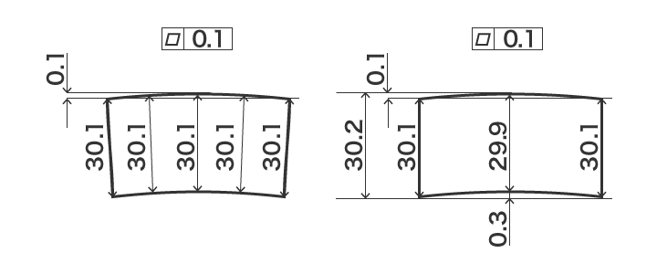
- Size tolerance and geometric tolerance are independent of each other. Therefore, the geometric tolerance (flatness) is within the indicated value (0.1) without being affected by size tolerance.
- ASME
- This drawing shows a size feature that is two parallel planes, and therefore the envelope principle is applied. The geometric tolerance (flatness) value changes depending on the material condition. The maximum material condition boundary (30.1) supersedes the size tolerance.