Observation of Clock Parts Using a Digital Microscope
Mechanical clocks are the representative device for precision microfabrication and they have a long history stretching back to the tower clocks of the 13th century. Although the turning of the gears was initially driven by weights, the method of using springs was discovered in the 15th century, leading to the miniaturisation of clocks. Wristwatches came into use in the latter half of the 19th century and remain in use to this day. The history of clock production in Japan is not as long, but ever since the Japanese company Seiko created their first quartz clocks in 1969, Japan has led the electronic clock movement.
This section provides an overview of clock parts and introduces examples of their observation using a digital microscope.
- What Are Movements and Ébauches?
- Frequency and Stone Count of Mechanical Clocks
- Frequency of Quartz Clocks
- Example Observations of Clock Parts Using a Digital Microscope
What Are Movements and Ébauches?
The movement is the mechanical part within the case of the clock that provides its motive power. There are two types of movements in mechanical clocks, those that are wound automatically and those that are wound manually. These days, automatically wound movements are the norm. Depending on the manufacturer, the model number assigned to the movement may be called the caliber.
Not all clock manufacturers create their own movements. Many manufacturers produce clocks by purchasing incomplete movements produced by movement manufacturers.
An incomplete movement is called an ébauche, a French word that means blank, outline, or sketch.
Frequency and Stone Count of Mechanical Clocks
Frequency of mechanical clocks
The movement of a mechanical clock is powered by a balance spring, which is inserted into the middle of the part called the balance wheel. The repeated expansion and contraction of the balance spring causes the balance wheel to gyrate back and forth (to vibrate).
The frequency indicates the number of vibrations of the balance wheel per hour.
Most current mechanical movements have frequencies of 28800 (8 vibrations per second). High-beat movements have frequencies that exceed this value, and low-beat movements have frequencies that are lower than this value.
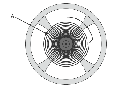
- A: Balance spring
Stone count
The shaft causes wear when the gears turn in a mechanical clock. Therefore, artificial rubies are used as bearings to minimise wear. In addition to the bearings, artificial rubies are also used for the easily worn pallets on the pallet fork.
The hardness of rubies is second only to diamonds, so rubies have been used as the stones in mechanical movements for a long time. The greater the stone count, the more high-grade and complicated the movement is.
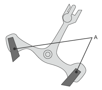
- A: Rubies
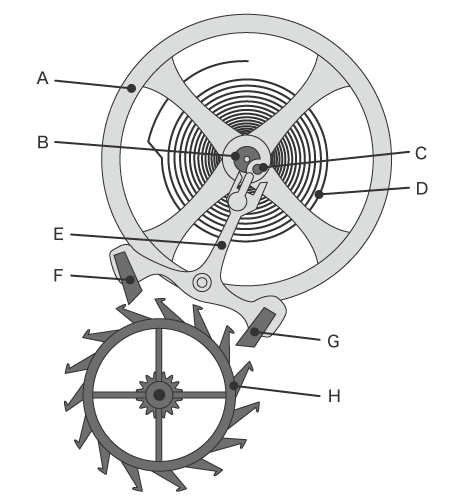
- A: Balance wheel
- B: Centre wheel top pivot
- C: Centre wheel jewel
- D: Balance spring
- E: Pallet fork
- F: Exit pallet
- G: Entry pallet
- H: Escape wheel
Frequency of Quartz Clocks
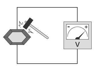
A quartz clock contains a crystal oscillator.
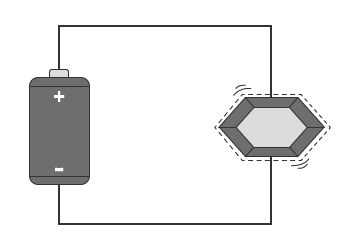
This crystal generates electricity when subjected to mechanical force. This is the piezoelectric effect. Conversely, it generates mechanical distortion when subjected to electricity (voltage). This is the inverse piezoelectric effect. Crystal oscillators use the inverse piezoelectric effect.
The typical frequency is 32.768 kHz. This is converted to 1 pulse per second (1 Hz) by an IC to move the second hand forward by 1 second.
Example Observations of Clock Parts Using a Digital Microscope
This section introduces the latest examples of observation of clock parts using KEYENCE’s VHX Series 4K Digital Microscope.
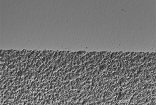
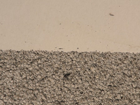
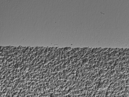
Observation of the surface processing status of a clock hand
Optical Shadow Effect Mode enables clear observation of surface textures.
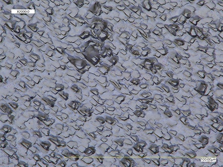
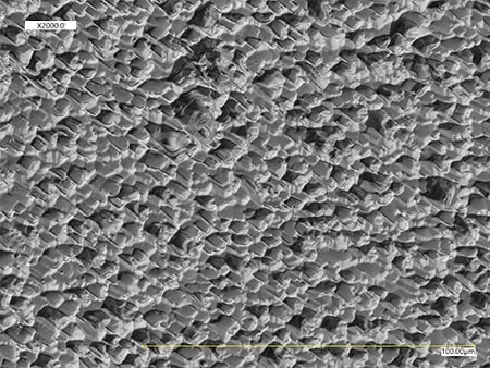
Observation of a silver vapor deposition surface on a crystal oscillator
Optical Shadow Effect Mode enables clear visualisation of the crystal directions.
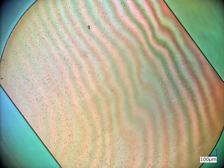
Observation of ground crystal surface
Differential Interference Contrast (DIC) and HDR enable visualisation of surface waviness.
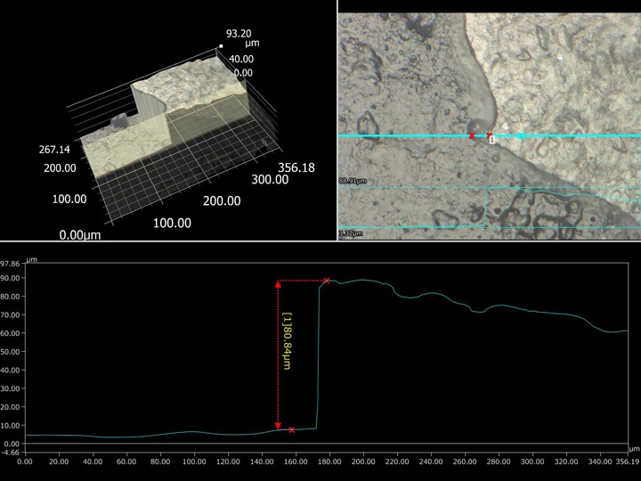
Clock belt coating film peeling (3D profile measurement)
3D profile measurement enables quantification of the coating film peeling.