
Débitmètres électromagnétiques à électrode non mouillée
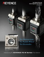
Série FD-M
Débitmètres électromagnétiques à électrode non mouillée Série FD-M
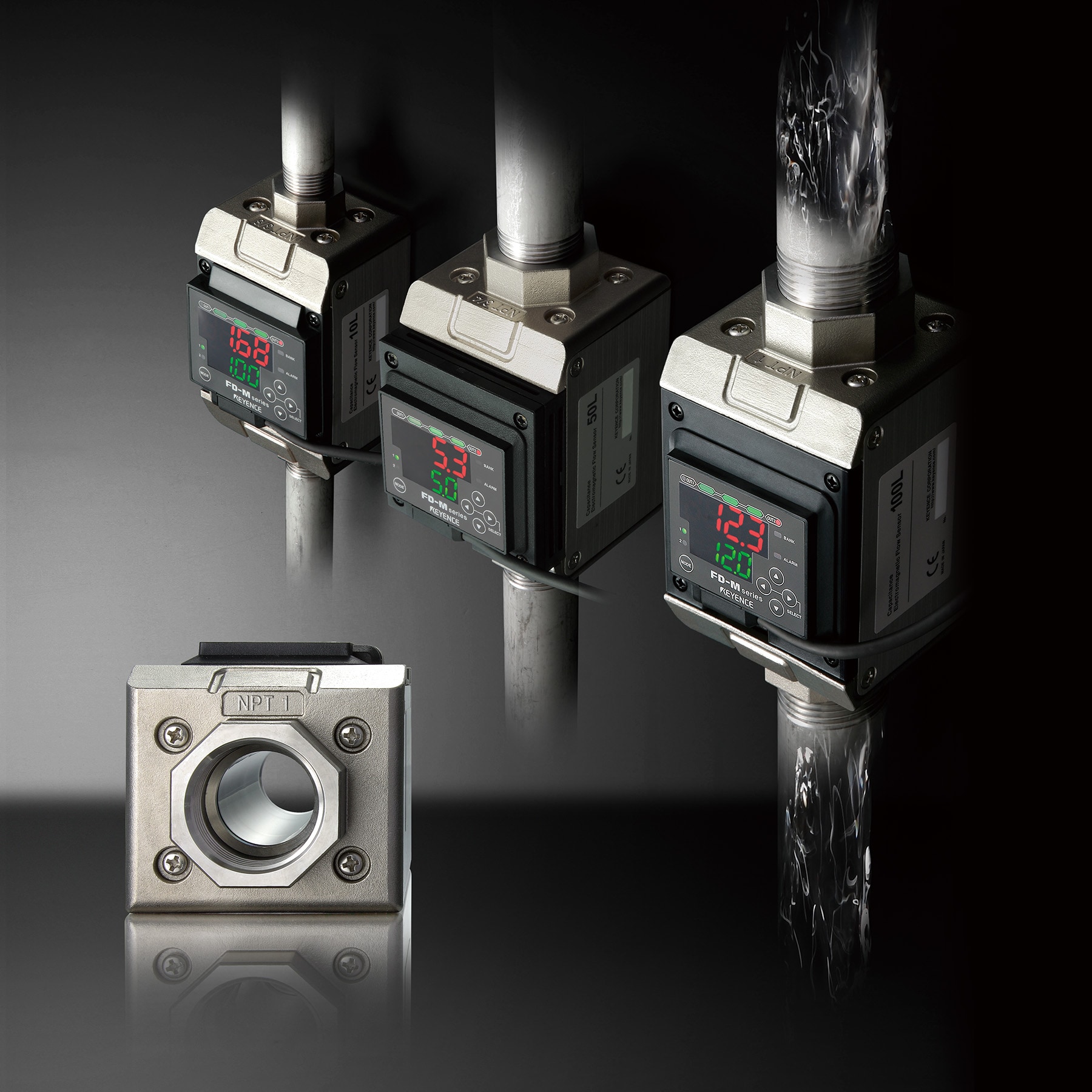
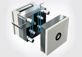
Aucune obstruction
Aucune turbine
Aucune électrode
La Série FD-M utilise la loi de Faraday pour déterminer le débit de liquides conducteurs.
Caractéristiques
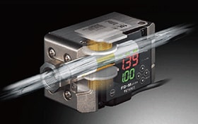
Aucune obstruction
La Série FD-M s’affranchit des technologies de mesure du débit classiques exploitant des turbines ou autres obstructions qui favorisent l’encrassement et les erreurs de détection. Sans pièce mobile, elle permet un écoulement libre du liquide lors de la mesure.
Polyvalence
La Série FD-M convient à un large éventail de procédés industriels, du meulage au moulage par injection, en passant par la soudure. Plus polyvalente que les capteurs classiques, elle s’adapte aisément aux variations de température et de liquides. De plus, sa capacité analogique élargit le champ des applications possibles.
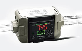
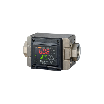
Simplicité d’utilisation
L’utilisation du débitmètre est intuitive grâce à un affichage facile à lire et de simples boutons de sélection-basculement à l’avant. Il se décline en une grande variété de modèles, pour une installation facile sur tout tuyau.